Measure, Measure and Measure Again
When I was on the road servicing stations, I kept an RF spectrum analyzer in my truck. I used it frequently to measure station performance and to verify that all RF output was within licensed parameters.
I discussed this in my article “How an RF Spectrum Analyzer Can Help You” in the Nov. 5 issue. But I am prompted to expand this discussion after seeing that the FCC recently issued a notice of violation to the owner of an FM transmitter in California.
Per the notice, FCC Rule 73.317 (d) states: “Any emission appearing on a frequency removed from the carrier by more than 600 kHz must be attenuated by at least 43 + 10 Log10 (Power, in watts) dB below the level of the unmodulated carrier, or 80 dB, whichever is the lesser attenuation.”
The station in question apparently had violated the rules. The owner was told to make it right at the site and with the FCC.
I suspect some translators of AM stations and LPFMs have never been measured and are in violation of FCC rules. Every licensee is responsible for keeping equipment in compliance. Remember, violations look bad on a station’s record at renewal time. There are often legal fees too.
This particular notice was published just when we thought the FCC wasn’t out there checking very much.
When to measure?
You should measure when you:
- Turn on a new station
- Replace a transmitter
- Install an auxiliary transmitter
- Turn on a translator for an AM station
- Add something as innocent as an RDS subcarrier
- Replace audio processing
Basically, measure whenever you make a change that might affect the RF bandwidth of the station. FCC rules haven’t changed in this respect — they are intended to protect ALL licensed users of the RF spectrum.
Documentation reports are required to be kept for two years. I recommend you keep the latest report on hand, even if it is older. The report is a benchmark for the future.
FM
Normally we think of the piece of radio spectrum for which a station is licensed. With +/– 75 kHz of FM modulation, each station is allotted 200 kHz of bandwidth. Allowed emissions decrease farther out from the assigned frequency.
Yes, a new transmitter will have been checked at the factory and found to be compliant with FCC rules, but that doesn’t mean it will play well in an RF environment.
The most common problem is when a signal from a nearby transmitter comes into a transmit antenna and mixes in the transmitter’s power amplifier. This is when we find mathematical sum and difference products that don’t make specs.
Example: A new transmitter is on 95.1 MHz while a nearby transmitter is on 94.1. They mix in the new transmitter and out comes an unwanted signal on 96.1 MHz. Oops!
An RF filter in the antenna line will be required here to knock down the incoming 94.1 so the mix product on 96.1 is less. Assuming that filter is of the bandpass type, it will further attenuate the unwanted 96.1 MHz. A filter will likely be required at the 94.1 station too.
Mixing of signals is inevitable; it is a matter of how much. The goal is to keep unwanted radiation sufficiently low so as to comply with the rules.
The FCC requires better in some special cases. I once had to prove that an FM station was RF clean into the aviation band (118 to 137 MHz). The mandate was to keep any radiation at or more than 88 dB below the station’s carrier in its 10 kW transmitter. The normal requirement is 80 dB. That extra 8 dB or more was difficult to measure, but I got it done so the station could go on the air.
There was an occasion when a 5 kW FM transmitter was being installed on a site that had three 20 kW transmitters. I knew there would be RF mixing products, but how much?
I connected a spectrum analyzer to an RF sample element in a section of the transmission line to the antenna. Holding my breath, I turned the 5 kW transmitter on and let the analyzer display all of the signals in the FM band. Then I turned the transmitter off and did the measurement again.
The difference between the two displays was dramatic, with many unwanted signals generated in the 5 kW transmitter from all the other signals. That gave me enough data to determine what type of filter was required to put the station in compliance.
For perspective, sum and difference RF mixing products are limited only by the bandwidth of the RF output network in the transmitter and the antenna. Solid-state transmitters are more susceptible than tube transmitters because their output networks are more broadband. I have seen where replacing a tube transmitter with solid-state required a new RF filter.
RF harmonics, as you may know, are mathematical multiples of a station’s operating frequency. For FM, that means measurements for compliance up to 1 GHz.
This is not normally a problem. However, one manufacturer ran into this and used tiles in transmitter power amplifier cavities to absorb unwanted frequencies. The military band ranges from 225 to 400 MHz. You don’t want to cause problems there!
I remember an instance where a 5 kW FM Collins transmitter passed all of the FCC-required measurements. But a cellular company called shortly after it went on the air to say they were getting unwanted signals in the 800 MHz cellular bands.
Investigation showed the signal to the antenna was clean but there was unwanted radiation coming from the transmitter itself — it was “cabinet radiation”! Copper hardware cloth over the air intake and exhaust ports helped but did not cure the problem.
Finally, I was able to tune the transmitter in such a way that minimized the unwanted signal. I left instructions describing how to tune the transmitter for best results, with only a 1% loss in PA efficiency.
Let’s say your transmitter VSWR meter shows high reflected power when everything else looks and sounds normal. This could be caused by a spur created in the RF exciter. Unwanted signals might be 200 to 600 kHz or more from the station’s frequency. It usually comes down to a failed capacitor or two in the exciter. At that point, the station’s signal is likely not in compliance with FCC rules.
AM NRSC
It was back in the early 1980s when annual AM proof of performance measurements went from audio frequency response and distortion measurements to RF occupied bandwidth measurements. Spectrum analyzers were becoming more affordable and yielded a much better look at transmitted signals.
[Related: “Get That Beat Out of Your Head!”]
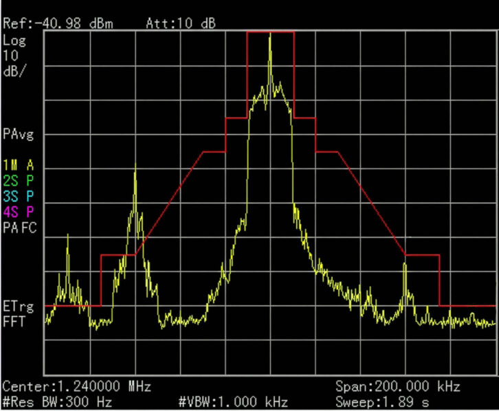
We are careful to look at the +/– 10 kHz spectrum of AM stations and also what goes out 100 kHz in each direction. When I was doing an annual NRSC measurement at 1240 kHz WJON Radio in St. Cloud, Minn., I detected a new signal at 1300 kHz. It was a mix product between WJON and the newly constructed 50 kW KYES on 1180 kHz.
The unwanted 1300 mix was above the FCC mask limit and had to be dealt with. The solution was to design and install a filter to notch 1180 kHz. That reduced the amount of 1180 kHz getting into the WJON transmitter and thus there was less mix product to be retransmitted. Figs. 1 and 2 show the before and after.
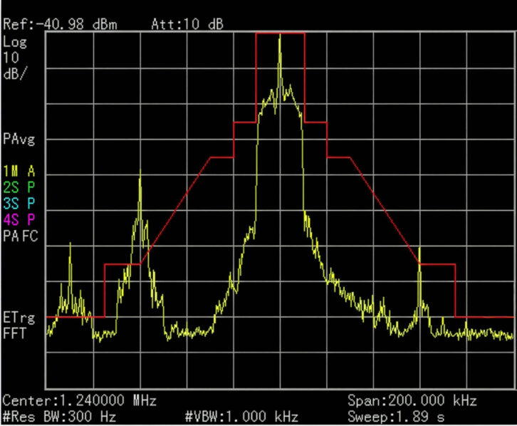
Yes, WQPM, 1300 kHz in Princeton, Minn., only 30 miles away was being interfered with until the filter was installed. The interference was heard as a mix of audio from WJON and KYES.
Delta Electronics, manufacturer of TCA RF ammeters, offers the SM-1 AM Splatter Monitor, which can be used in place of a spectrum analyzer when doing NRSC compliance measurements.
STL
Studio-transmitter links can get into trouble too.
Mounting two STL transmit antennas close together can create a situation where there is cross-coupling of the two signals. Multiple 950 MHz signals can and will mix in the output amplifiers of STL transmitters. Mix products can interfere with other local STL systems.
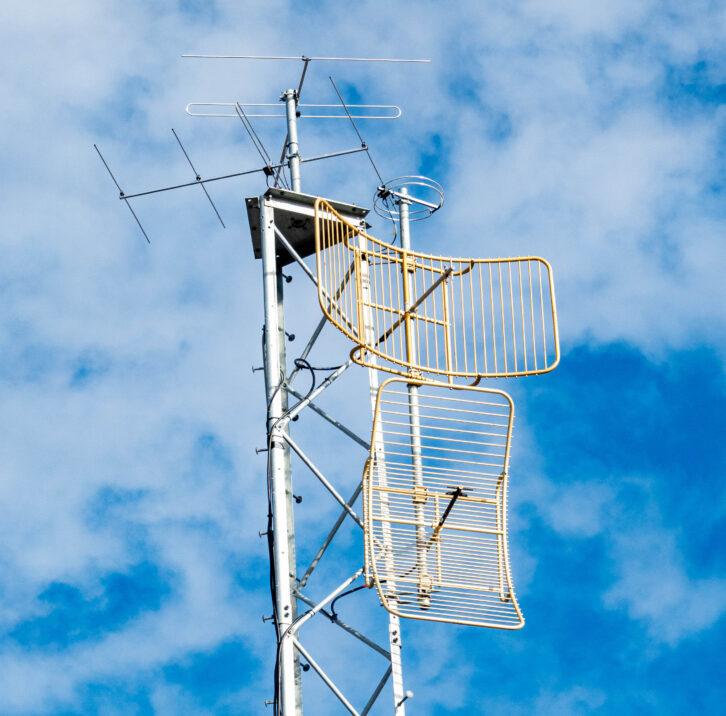
I like to mount STL transmit antennas a minimum of 10 feet apart to avoid this problem. The dishes in Fig. 3 were installed by a “professional” tower crew but with no engineer overseeing the project.
Diligence
As I mentioned, annual measurements are required on AM stations. FM stations don’t face that requirement but are just as susceptible to problems, if not more so.
Don’t walk away after a successful set of measurements and think you are done. When you learn that a nearby station has signed on or made a change, grab a spectrum analyzer and check again. You might find RF mixing products that don’t make FCC specs.
We live in an RF-rich environment where unintentional signals are created and must be dealt with. It is good engineering practice to check whenever there is a question.
Comment on this or any story. Email radioworld@futurenet.com with “Letter to the Editor” in the subject line.
The post Measure, Measure and Measure Again appeared first on Radio World.